Projects/LDS at PARCO
Flagship project · Pioneer

Design, Supply & Commissioning of one of Pakistan's first RTTM‑based pipeline leak detection systems

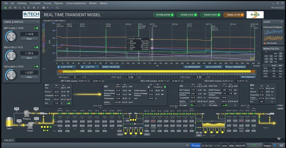
Real-time transient model leak detection and batch tracking on PARCO's 364 km MFM multi-product pipeline.

Customer
PARCO Pak-Arab Refinery Limited
OEM
Berlin
Role
Project engineer
Duration
Mar 2019 – Oct 2021

01 · Introduction

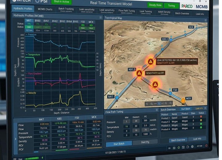
PARCO’s MFM Pipeline carries High-Speed Diesel and Motor Gasoline through 364 kilometres of underground line. Before this project, the line had no real-time leak detection; operators relied on batch reconciliation and physical patrols. The brief was a Real-Time Transient Model (RTTM) system: a continuous hydraulic simulation running in parallel with the pipeline, where deviations between the model and field data indicate either a leak or a process upset.

The scope covered full delivery: RTTM implementation; Model-Compensated Mass Balance as the primary leak detection method; Pressure Gradient and Negative Pressure Wave methods for leak location; custom applications for batch tracking, pig tracking, and alarm management; field instrumentation and data-transmission integration; an RTU application for NPW and continuous pressure data; and final tuning to acceptance criteria. After commissioning, the work was extended to operator and engineer training, a user manual, and an engineering reference guide.

The system met every benchmark parameter across the 364 km line, with leak sensitivity studies to API RP 1149, and was accepted by PARCO. It became INTECH’s first RTTM-based leak detection delivery and the reference project for its LDS product line.

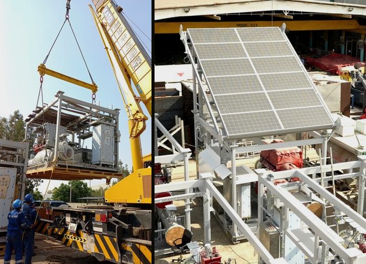
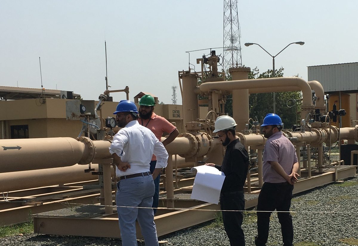
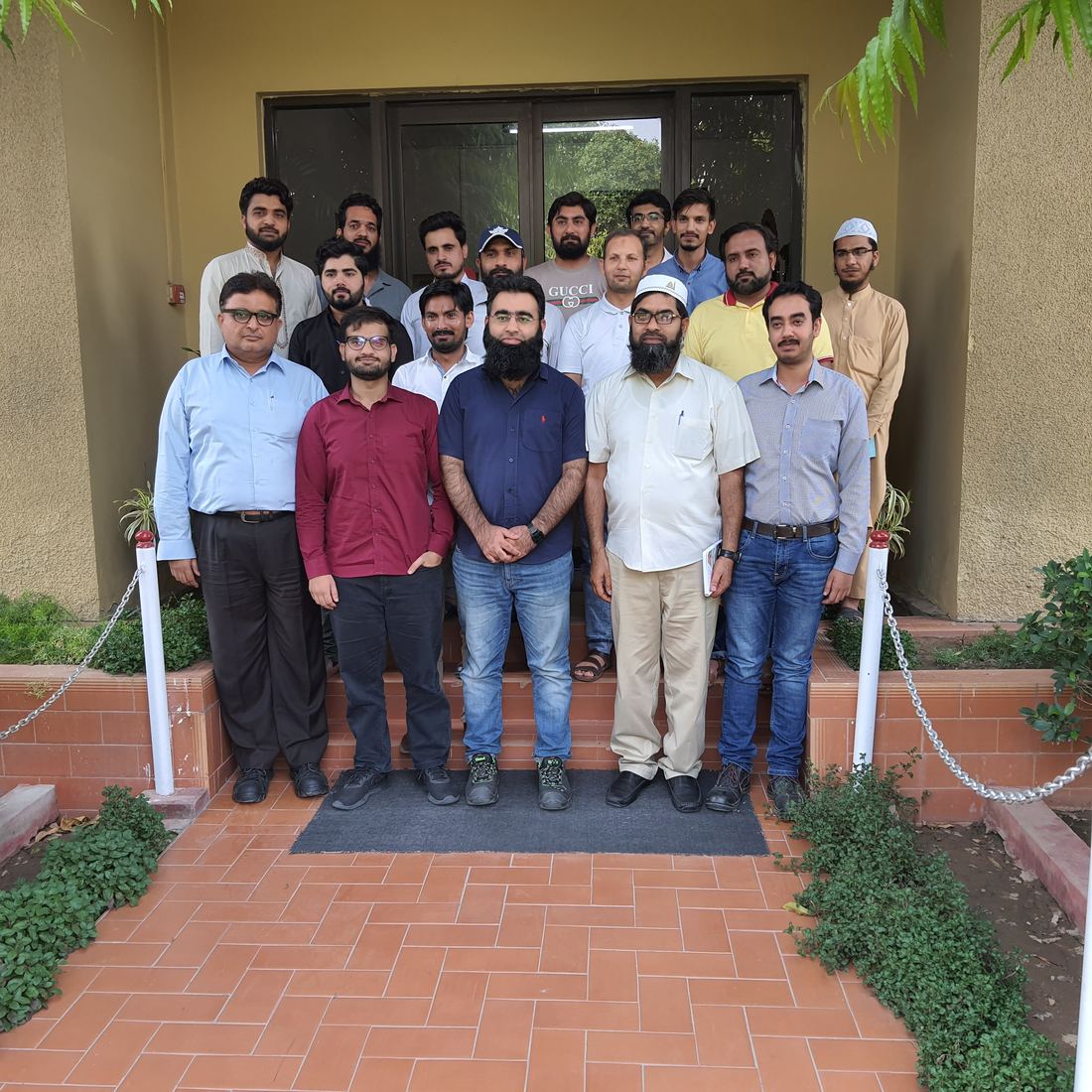
Site commissioning at PARCO MFM pipeline
Site commissioning, MFM pipeline

The sections below show how it was delivered.

02 · Five technical challenges

The project’s main engineering work, in five parts.

Each challenge was a gap between the customer’s acceptance criteria and the OEM product’s standard capability. The sections below describe how each gap was closed.

01 / 05

Pressure Gradient Method extension for high-sensitivity pilferage detection

A requirement the OEM considered outside the product’s standard capability.

Problem

Field pressure, flow, and temperature transmitters communicated with the control system over a radio link rather than fibre. This introduced variable latency across the instruments, so the Pressure Gradient algorithm was comparing pressure readings taken at slightly different times. With this constraint, the customer’s required leak location accuracy under low-flow pilferage conditions could not be met with the OEM’s default configuration.

Approach

Worked through the problem in m42, PSI’s proprietary scripting language, by elimination. Three candidate approaches were tested: a most-stable-calculation method that selected the location with the lowest variance across the leak-duration window, a threshold-triggered method that recorded the calculation at the moment warning thresholds were breached, and a first-response method that took the earliest calculated location at pilferage onset. Calculation-historian data from repeated simulated pilferage events was used for testing.

Solution

The historian data showed that, despite the latency errors, the software’s first response at the onset of pilferage was consistently closest to the true leak location. Using that first response, with the warning-threshold breach as the trigger to lock the calculation, met the customer’s accuracy benchmark on most test events. The extension became the basis for how the OEM’s product handles radio-link-constrained installations.

Value

Both PSI and PARCO formally acknowledged the extension. It became the reference approach for handling Radio-Link-constrained installations in this product class.


02 / 05

Alarm suppression and grid-frequency handling on the NPW method

Driving false-alarm rate down without losing genuine-leak sensitivity.

Problem

The Negative Pressure Wave method needed low pressure-variation thresholds to achieve the required leak location accuracy. Low thresholds made the system sensitive to two noise sources: random fluctuations in National Grid frequency at the initial pumping stations, which produced pressure waves similar to leak-induced waves, and routine equipment operations (pump starts and stops, tank level changes, standby switching, valve actuations), which produced comparable signatures.

Approach

Two investigations ran in parallel. For grid frequency, multiple wave-generation records were correlated with frequency-variation data to identify how grid-induced waves differed from leak-induced waves. For equipment, pumps, storage tanks, standby equipment, pressure return valves, and non-return valves at several pumping and receiving stations were modelled in the OEM software, so that equipment-induced waves could be identified at source rather than filtered later.

Solution

For grid frequency, thresholds were narrowed against a per-cycle calculation-time delta flag, which removed the false alarms attributable to grid-frequency variation. For equipment, per-equipment suppression-time windows were configured from the integrated-data side, optimising the cumulative suppressed time without compromising genuine-leak detection latency.

Value

The NPW method stabilised at the required accuracy benchmark with the false-alarm rate brought to acceptable operating levels. The customer accepted the system in this region.

03 / 05

Leak detection in the low-pressure receiving region

A physical limitation the default configuration could not resolve.

Problem

The receiving end of the pipeline operated below 1 bar. Pressure waves attenuate severely in low-pressure conditions, and NPW-based leak location could not resolve events in this region to the required sensitivity. Default product configuration had no answer for this condition.

Approach

Started from the physics of pressure-wave attenuation at low pressure and ran field-instrumentation integrity checks alongside slack-flow analysis. In parallel, reviewed a published paper by Atmos International on the same problem on a Romanian crude-oil pipeline network, where NPW propagation had been restored by introducing controlled back-pressure through Pressure Safety Valve pinching at the receiving end.

Solution

Replicated the PSV-pinching methodology, adapted to the MFM Pipeline's specific topology and operating profile. The increased receiving-end pressure removed the slack-line condition and restored NPW wave propagation to the benchmark sensitivity in this region.

Value

The benchmark was met in a region the default configuration could not handle. Using a published method from another vendor’s work, rather than limiting the investigation to the OEM’s documentation, became a practice repeated on later projects.

04 / 05

Drag Reducing Agent handling across the operating envelope

The accuracy benchmark had to hold across all operating modes, not only steady state.

Problem

Drag-reducing agent reduces frictional pressure losses and lifts achievable flow rates. With DRA in the line, the pressure profile differs materially from the non-DRA baseline, and the leak-location accuracy benchmark had to hold under DRA conditions as well. No universal formula exists for predicting DRA behaviour across all manufacturers, pipeline types, and operating conditions.

Approach

Identified the DRA manufacturers in use on the line, ran trial pumping runs at varying injection rates, and recorded the pressure-profile response. Built an empirical model from the trial data, based on the manufacturers actually used on this pipeline.

Solution

An empirical formula that predicts pressure-profile changes from the live RTTM flow-rate and pressure values plus the operator-supplied DRA injection rate. The prediction updates in real time as pipeline conditions change. The accuracy benchmark held under DRA.

Value

The acceptance criteria held across the full operating envelope: non-DRA, DRA, steady state, pumping, pigging, re-injection, and take-off.

05 / 05

RTU application for NPW and continuous pressure data

Bridging the field-instrumentation layer into the leak-detection model.

Problem

The NPW method and the continuous-pressure dataset for the RTTM both required field data delivered at a cadence and integrity the standard SCADA polling could not provide on this Radio-Link-served line. The leak-detection model needed a data path that respected its calculation cycle.

Approach

An RTU-resident application was specified, scoped to deliver NPW samples and continuous pressure data to the leak-detection layer at the cadence and timestamp fidelity the model required. Instrument signal handling, communication framing, and timestamp synchronisation were defined at the RTU layer rather than the SCADA layer, so that the leak-detection model received data that already met its integrity needs.

Solution

The RTU application was deployed across the pumping and receiving stations and integrated with the SCADA / RTTM stack. The leak-detection model received the pressure and NPW data on its own calculation cadence, not the SCADA polling cadence.

Value

This layer supplies the data the PGM, NPW, and MCMB methods depend on. A weak data path here would have limited every leak detection method downstream, so it was treated as a prerequisite for the system.

03 · Knowledge Transfer

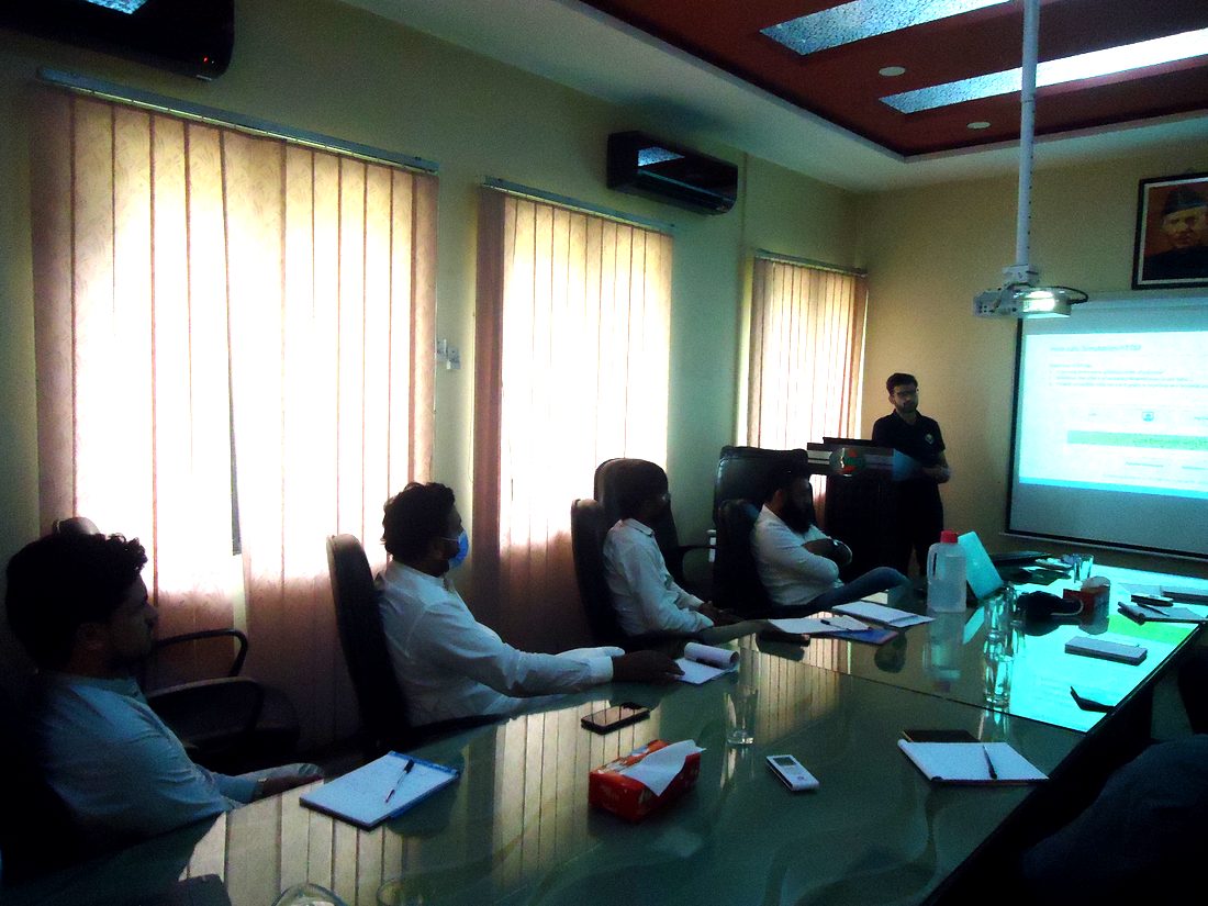
Operator and engineer training, delivered on-site

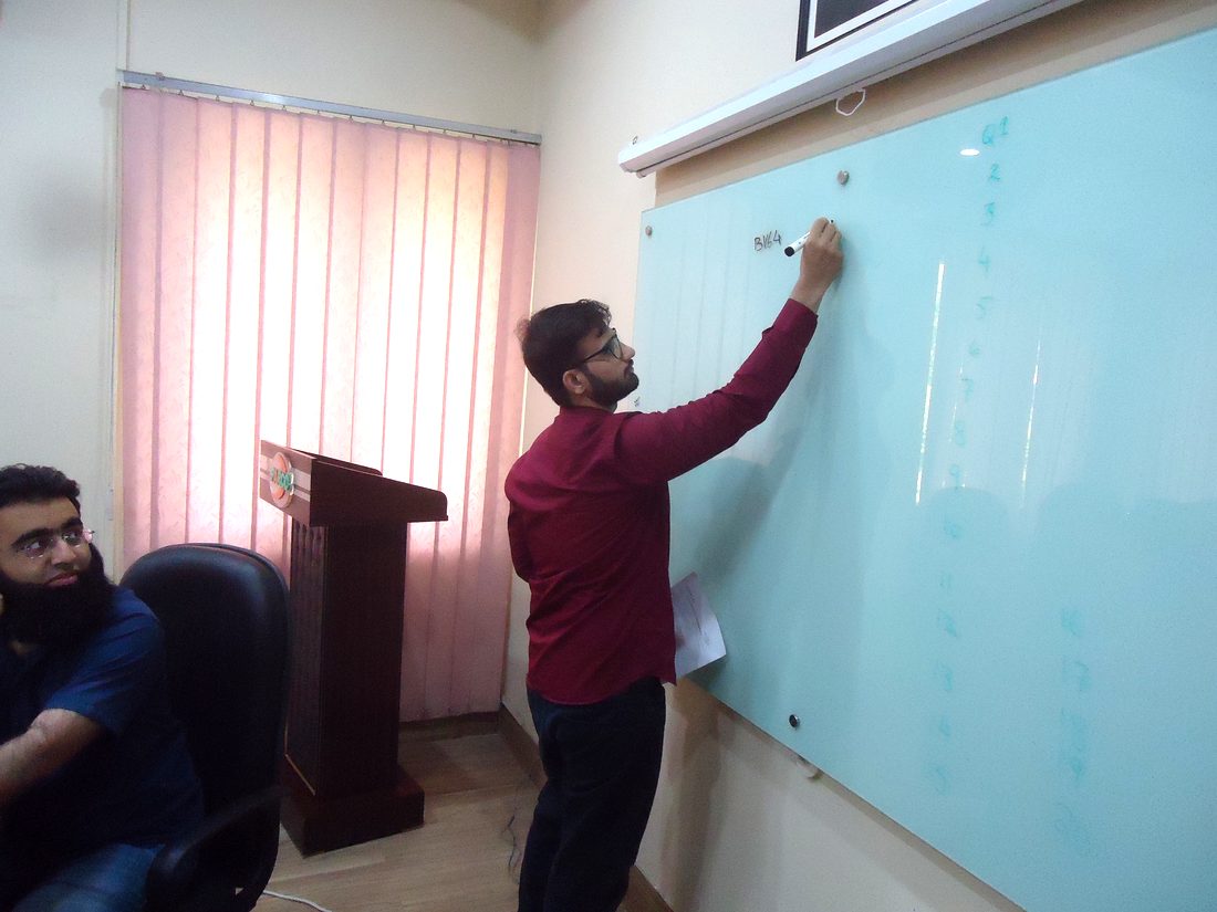
After commissioning, the customer asked the team to return and run sessions for the people who would operate the system day to day. Standard formats were established for formal training for LDS Products for future customers.

Two tracks ran in parallel, separated by audience and by the depth of access each group needed.

Track 01 · Operators
Using the system and interpreting its output
For the control-room team: operating the LDS interface, interpreting alerts, distinguishing process upsets from genuine leaks, and responding to model and field indications. Delivered with an Operations Manual covering daily shift procedures, alarm response, and system use.
From
On-site training sessions
What
  • Using the LDS interface
  • Reading alerts
  • Upset vs genuine leak
  • Alarm response
To
PARCO control-room operators
Operations Manual
Track 02 · Engineers
Engineering configuration of the solution
For PARCO’s engineering staff. Modifying graphics, scripts, and logic; the reasoning behind the configuration choices; how to extend the system as the pipeline’s operating envelope changes. Delivered with a dedicated Engineering Reference Guide and leak sensitivity studies to API RP 1149 (1993 and 2015 editions).
From
Engineer-to-engineer sessions
What
  • Graphics and scripts
  • Configuration logic
  • Design rationale
  • Extending the system
To
PARCO engineering staff
Engineering Reference GuideAPI RP 1149 studies

04 · Acknowledgement

What the customer and the team said

★ ★ ★ ★ ★ CSS rating
“Getting better and better after every project. Excellent training delivered up to the mark.”
Syed Abdullah Hassan
Chief Engineer, SCADA Systems
PARCO (Pak-Arab Refinery Limited)
PARCO LDS · Customer voice
Muhammad Faisal
“It can be said without any doubt that Abubakar is a key team player and a major contributor to the success of engineering projects. His work on advanced Leak detection systems for development of application modules involving complex scripting was highly acclaimed by both software vendor and client. A quick learner with the ability to execute tasks at a faster pace.”
Muhammad Faisal
Pipeline Leak Detection Solutions Architect
INTECH Automation & Intelligence
PARCO LDS · Peer architect

Explore my Work

Five flagship deliveries